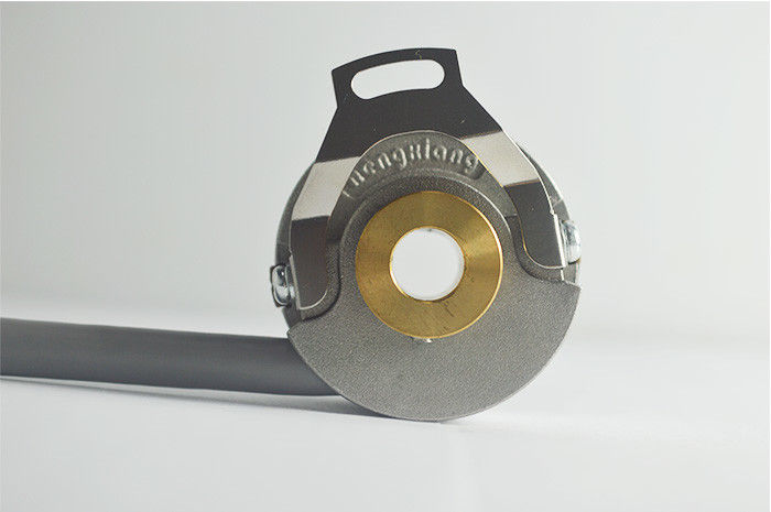
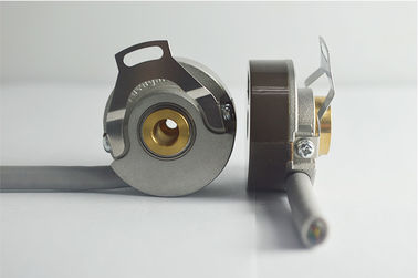
14400 high resolution servo motor rotary encoder line driver IC-HD7 output KN35 DC8-30V
Key Feather of KN35 encoder
Brand: HENGXIANG
External diameter: 35mm
Thickness: 18mm
Installation dimension: R13.5mm, R14.5mm, R20mm
Hollow shaft type: blind hole; through hole, taper hole
Supply voltage: DC5V ; DC8--30V
Sock(endure): 490m/s2 ,11 ms three times for X,Y,Z direction individually
Shell Material: die cast aluminum
Certification: CE
Parameter table for KN35 incremental encoder
| Items | Basic parameters |
| Encoder type | Incremental encoder |
| Hollow shaft diameter | 6mm,7mm;8mm;10mm |
| Resolution | 1024;2048;2500;3600;5000;7200;10000;14400 |
| 1000/4;1000/6;1000/8;1024/4;1024/6;1024/8;2000/4;2000/6;2000/8;2048/4;2048/6;2048/8;2500/4;2500/6;2500/8;4096/4;4096/6;4096/8;5000/4;5000/6;5000/8 | |
| Output phase | Phase A+,B+,Z+,A-,B-,Z-,U+,V+,W+,U-,V-,W- |
| Supply voltage | DC5V ; DC8--30V |
| Outlet type | Cable out from side |
| Output mode | NPN/PNP(Open Collector Output) |
| Voltage output | |
| Push-pull output | |
| line drive (26LS31) TTL | |
| line drive(DC8-30V) HTL | |
| TTL(DC5V) phase ABZ are back of phase UVW | |
| Protection grade | IP40 |
| Cable length | 500mm |
| Consumption current | 100mA MAX |
| Top response frequency | 300KHZ |
| Allowable ripple | ≤3%rms |
| Load Voltage | ≤DC30V |
| Insulation strength | AC500V 60s |
| Insulation resistance | 10MΩ |
| GND | not connect to encoder |
| Mark to Space ratio | 45% to 55% |
| starting torque | less than 5.9x 10⁻³ N.m |
| Intertia moment | less than 1.5x 10⁻⁶kg.m2 |
| Shaft load | Radial 30N; Axial 20N |
| Slew speed | 5000RPM |
| Bearing life | 1.5x10⁹ revs at rated load(100000hrs at 2500RPM) |
| Environmental temperature | Operating:-20 ~+100°C;storage:-25 ~+100°C |
| package | Carton box |
| Net weight | About 80g (with package) |
Encoder Operation method
With proper connections you can use the Push Pull interface to replace true open collector circuits by using an external diode connected in a way to limit the direction of the current for RS422 (TTL) circuits provide a constant 5 V signal level that is not dependent on the supply voltage. Two supply voltage ranges can be selected: From 4.75 to 5.5 VDC (can be used to replace open collector output drivers) or from 8 to 30 VDC. Using differential signals the output fully complies to the RS422 standard.
The differential outputs have the highest frequency response capability and the best noise immunity. To ensure this the receiver should also be a differential.
Replacement of Older Output Drivers
A logic gate interprets certain input voltages as high (logic 1) or low (logic 0).
TTL (transistor-transistor-logic): A signal above 2 V is interpreted as logic 1 and a signal less than 0.8 V is interpreted as logic 0. The output voltage ranges between 0-5 V.
HTL (high-threshold-logic): A signal above 3 V is a logic 1 and a signal less than 1 V is a logic 0. The high output signal level is dependent from the supply voltage. Because of the higher voltage difference between logic 0 and 1, the HTL logic is more immune to interference and more resistant against electrical noise.
Mechanical degree is the actual rotation of the shaft in degrees. Electrical degree is used for electrical signals. The required time for completing one alternating voltage/current cycle is defined as 360 electrical degrees (el°). For incremental encoders, one cycle is equal to one complete pulse. With a given PPR the electrical degree can be converted to mechanical degree for any incremental encoder.
![]()
Our products are sold all over the world, you can rest assured.