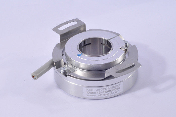
Through hole 16mm heavy duty encoder K58 encoder 28800 pulse line driver output
Product Description
Simple introduction of K58 rotary encoder
Encoder type: Incremental encoder
External diameter: 58mm
Thickness: 24mm
Installation dimension: R34.1mm(spring plate 58T64)
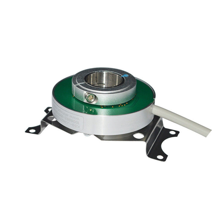
Hollow shaft type: clamping ring at prior or clamping ring at rear
Hollow shaft diameter: 15mm,16mm,18mm;20mm;22mm
Shaft load: Radial 50N; Axial 30N
Bearing life: 1.5x10⁹ revs at rated load(100000hrs at 2500RPM)
Specification for K58 series
|
Items |
Basic parameters |
|
Brand |
HENGXIANG |
|
Encoder type |
Incremental encoder |
|
External diameter |
58mm |
|
Thickness |
24mm |
|
Allowable ripple |
≤3%rms |
|
Load Voltage |
≤DC30V |
|
GND |
not connect to encoder |
|
Mark to Space ratio |
45% to 55% |
|
starting torque |
less than 9.8 x 10⁻³ N.m |
|
Intertia moment |
less than 6.5x 10⁻⁶kg.m2 |
|
Shaft load |
Radial 50N; Axial 30N |
|
Top REV |
3000RPM |
|
Bearing life |
1.5x10⁹ revs at rated load(100000hrs at 2500RPM) |
|
Environmental temperature |
Operating:-20 ~+85°;storage:-25 ~+90° |
|
Environmental humidity |
Operating and storage: 35-85%RH(noncondensing) |
|
Vibration(endure) |
Amplitude 1.52mm,5-55Hz,2 hours for three axis individually |
|
Sock(endure) |
980m/s2 ,11 ms three times for X,Y,Z direction individually |
|
Shaft Material |
Stainless steel |
|
Shell Material |
die cast aluminum |
|
Cable length |
1000mm(cable with shielding) |
|
Protection grade |
IP50 |
|
Cable length |
1M (cable length could be added appropriately by |
|
|
require, but it need payment individually) |
|
Certification |
CE |
|
package |
Carton box |
|
Net weight |
About 150g (with package) |
![]()
Principle of encoder
he differential outputs have the highest frequency response capability and the best noise immunity. To ensure this the receiver should also be a differential.
Replacement of Older Output Drivers
A logic gate interprets certain input voltages as high (logic 1) or low (logic 0).
TTL (transistor-transistor-logic): A signal above 2 V is interpreted as logic 1 and a signal less than 0.8 V is interpreted as logic 0. The output voltage ranges between 0-5 V.
HTL (high-threshold-logic): A signal above 3 V is a logic 1 and a signal less than 1 V is a logic 0. The high output signal level is dependent from the supply voltage. Because of the higher voltage difference between logic 0 and 1, the HTL logic is more immune to interference and more resistant against electrical noise.
Mechanical degree is the actual rotation of the shaft in degrees. Electrical degree is used for electrical signals. The required time for completing one alternating voltage/current cycle is defined as 360 electrical degrees (el°). For incremental encoders, one cycle is equal to one complete pulse. With a given PPR the electrical degree can be converted to mechanical degree for any incremental encoder.
About Encoder Vibration
Vibration acting on an encoder always cause wrong pulse easily.
So we have to pay more attention to encoder working place.
The more pulse per round, the narrower groovy spacing of grating, ore effect to encoder by vibration, when motor speed is low or even stopped, vibration acting on encoder shaft or encoder shell would cause grating vibration, in this way, encoder might show wrong pulse signal.
Our products are sold all over the world, you can rest assured.