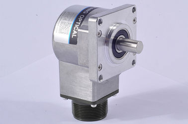

Conventional incremental encoder totem pole output S52F flange encoder with radial socket
About Encoder Vibration
Vibration acting on an encoder always cause wrong pulse easily.
So we have to pay more attention to encoder working place.
The more pulse per round, the narrower groovy spacing of grating, ore effect to encoder by vibration, when motor speed is low or even stopped, vibration acting on encoder shaft or encoder shell would cause grating vibration, in this way, encoder might show wrong pulse signal.
K52F Series encoder Specification
| Items | Basic parameters | |
| Brand | HENGXIANG | |
| Encoder type | Incremental encoder | |
| External diameter | 52mm | |
| Thickness | 44mm | |
| Flange dimension | 52mm x 52mm | |
| Installation dimension | 44mm x 44mm | |
| Shaft length | 16mm | |
| Solid Shaft diameter | 10mm(D shape) | |
| Output mode | NPN Collector open circuit output | |
| Voltage output | ||
| Push-pull output | ||
| Difference output | Long line drive (26LS31) | |
| Compatible RS422 | ||
| Long line drive (RT7272) | ||
| Protection grade | IP50 ; IP65 | |
| Cable length | 1M (cable length could be added appropriately by | |
| require, but it need payment individually) | ||
| Consumption current | 100mA MAX | |
| Environmental temperature | Operating:-20 ~+85°;storage:-25 ~+90° | |
| Environmental humidity | Operating and storage: 35-85%RH(noncondensing) | |
| Vibration(endure) | Amplitude 0.75mm,5-55Hz,2 hours for three axis individually | |
| Sock(endure) | 490m/s2 ,11 ms three times for X,Y,Z direction individually | |
| Shaft Material | Stainless steel | |
| Shell Material | die cast aluminum | |
| Cable length | 1000mm(cable with shielding) | |
| Certification | CE | |
| package | Carton box | |
| Net weight | About 300g (with package) | |
Lead time
1. for 1-10 samples: 3-5 working days
2. for 20-50 mass production: 7-10 working days
3. for over 100pcs, production will be discussed with customers and ship on time
Packing Details
Each single encoder is packed into a single safe carton with protecting bubble.
Then all encoders will be put into a bigger carton to prepare shipment.
Principle of encoder
With proper connections you can use the Push Pull interface to replace true open collector circuits by using an external diode connected in a way to limit the direction of the current for RS422 (TTL) circuits provide a constant 5 V signal level that is not dependent on the supply voltage. Two supply voltage ranges can be selected: From 4.75 to 5.5 VDC (can be used to replace open collector output drivers) or from 8 to 30 VDC. Using differential signals the output fully complies to the RS422 standard.
The differential outputs have the highest frequency response capability and the best noise immunity. To ensure this the receiver should also be a differential.
Replacement of Older Output Drivers
A logic gate interprets certain input voltages as high (logic 1) or low (logic 0).
TTL (transistor-transistor-logic): A signal above 2 V is interpreted as logic 1 and a signal less than 0.8 V is interpreted as logic 0. The output voltage ranges between 0-5 V.
HTL (high-threshold-logic): A signal above 3 V is a logic 1 and a signal less than 1 V is a logic 0. The high output signal level is dependent from the supply voltage. Because of the higher voltage difference between logic 0 and 1, the HTL logic is more immune to interference and more resistant against electrical noise.
![]()